you are here: home > operations > starter
Setting up and using your first Märklin Z starter set
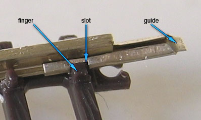
1) joining track
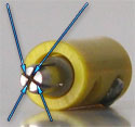
The track consists of plastic ties with rails on top, held on by having been slid between small fingers on either side of each rail. At one end of each rail is the rail joiner. A portion of the rail joiner is secured to its rail by means of small slot through which one of the tie's plastic fingers rests in. Extending from the rail joiner is a very thin flat guide that will slide under the rail of the adjoining track.
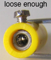
When you join two pieces of track line up both rails and make sure the thin flat extension of each of the rail joiners slips between the plastic rail support and the bottom of each of the joining rails. It's easy to bend the small extension if things aren't lined up - and after you bend it back in place a couple times it will break off. You need this piece intact for good electrical conductivity.
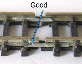
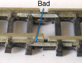
If the joining rail is not slid into the the joiner it will rest on top of the crimp and your rail heights will be uneven at the transition. Run your finger along the top of the joined rails - the transition should be smooth.
You can buy more track joiners. Märklin sells part #8954 - a package with 10 Insulated and 20 regular rail joiners.
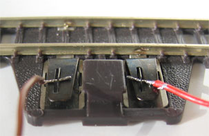
2) wiring the feeder track
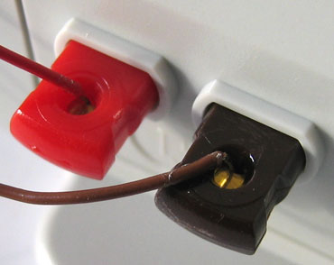
Most starter sets will have either a battery or a plug-in-the-wall power pack. You should find a feeder track and connecting wire in the box. With the feeder track (the piece with the two metal spring contacts) orientated such that the contacts are on the side closest to you, connect one end of the brown wire to the left terminal and one end of the red wire to the right one. This will connect brown to the "inside" rail and red to the "outside". Inside and outside can be ambiguous depending on your layout, but if you set you track up like the picture on the box or the diagram in the SET booklet that should have come with your set, then inside and outside are meaningful. Where red and brown are connected is a convention used by Märkin and although you can flout it, conforming to the convention will result in fewer surprises down the road when your track plan grows. Connect the wires to the feeder track with the power pack unplugged from the wall (or the battery removed from a battery operated power pack).
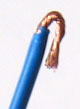
If the wires don't already have a small amount of solder on them (tinned), prepare them by twisting each exposed (uninsulated) wire end so the strands are not "sticking out". To connect the wire to a feeder terminal press the free end of the horizontal contact down enough to expose the hole in the vertical contact protruding through the horizontal contact.
Feed the wire through hole such that when you release pressure on the horizontal contact the spring tension will hold the wire fast. Be sure the uninsulated wire is what's being held in place not the insulated part. Also check the exposed end of the wire is not protruding so far as to touch the other contact or the exposed end of the other wire.
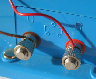
For a plug-in-the-wall power pack you'll now connect the other ends of the brown and red wires to the terminals on the power pack.
The older (blue) power packs (e.g., 6727) have screw terminals with colored bands for the track power. Connect the free ends of the brown and red wires to the appropriate terminals by unscrewing the knurled ring to reveal a hole.
Slide the wire through the hole and tighten the ring. Be sure the uninsulated part of the wire is passing through the hole and no uninsulated wire is touching any other terminal.
The newer (white) power packs (e.g., 67271) have color coded spring tension terminals. Push the terminal in towards the power pack to reveal the hole.
Slide the wire into the hole and release the terminal. Be sure the uninsulated part of the wire is passing through the hole and no uninsulated wire is touching any other terminal.
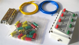
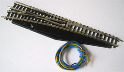
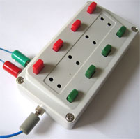
3) wiring electric turnouts and crossovers (switches)
If your starter set came with electric switches then it should have also come with one or more control boxes (7272 or 72720) to control them, wire and plugs to connect them and a distribution strip (7209 or 72090) . The 72720 control boxes are the newer type introduced in 2004) and mate with the modern plugs that have extra insulating features (likewise with the 7209 and 72090 - the extra "0" is for "m0dern"). I haven't had these plugs and boxes in my hands but judging from the pictures in the catalog I think they are wired the same as the old ones.
Each switch has a yellow wire and two blue ones. When the electrical path travels through the yellow wire and one of the blue wires the switch will direct traffic one way. When the electrical path travels through the yellow wire and the other blue wire, the switch will direct traffic the other way.
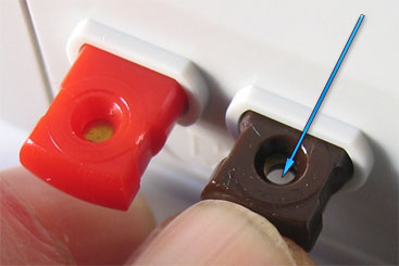
First, install a plug on the end of each wire of each switch. A yellow plug for the yellow wire, a red plug for one of the blue wires and a green plug for the other blue wire. The wire is inserted in the end of the plug and the screw is tightened, pressing the uninsulated wire against the inner wall of the plug.
If the wire ends aren't already prepped with solder, twist each exposed (uninsulated) wire end so the strands are not "sticking out" as you did with the feeder connection. Bend the uninsulated part of the end of the wire just a little bit beyond the point were the insulation stops back over itself and the insulated part of the wire. You'll have insulated wire, a little uninsulated wire, a 180º bend and the rest of the uninsulated wire.

Loosen the screw on the plug casing until, looking inside the plug, you see the screw is not protruding into the interior - or at least not much. If you loosen the screw too much it will fall out - be prepared.
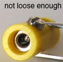
Insert the bent wire into the plug bend first, and tighten the screw securely. Unless you're very unlucky the screw the will push the insulated part of the wire against the uninsulated part against the interior wall of the plug. If you are unlucky we'll find out later and redo it. When you tighten the screw make sure the screw is centered in its hole in the plug's shell so you're tightening against the wire and not against the plastic shell.
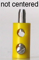
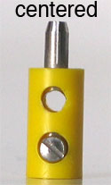
After you've tightened the screw give a gentle tug on the wire - it shouldn't be loose and it shouldn't come out of the plug.
With plugs on the ends of all the wires on your switches, insert each of the yellow plugs into the distribution strip and insert the red and green plugs into the control boxes. Each control box will accommodate up to four switches. With the control box orientated so the red buttons are at the top insert the red plug from one switch into the leftmost socket in row of eight sockets of the control box. Insert the green plug from the same switch into the next socket. Repeat for each switch.
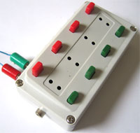
If you have more than four switches you'll use more than one control box. The screws that came in the package with the plugs can be used to screw down the control boxes. Use them in place of the bottom-left and top-right screws that are already installed in the boxes.
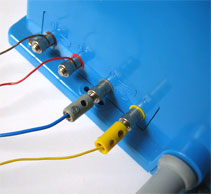
Now that your switches are all connected to something we need to connect those things to the power pack. When you hooked up your feeder fire you found the red and brown terminals on the power pack are for track power - 0-10V DC. The yellow and grey terminals are for accessories - 16V AC. Your starter set came with a spool of blue wire and a spool of yellow wire. You'll need to strip the about 3/8" of insulation from each end of the wire from each spool. If you don't have wire strippers there are a few other techniques to strip wire. There is the "using your front teeth" method which I stopped employing when I was old enough to have to pay my own dental bills. There is the "brute force fingernail" method where you pinch the wire between two fingernails just tightly enough to score the insulation and pull hard - hoping you break the insulation and not the wire or your nails. In a modification of this technique use a blade to score the insulation first - make sure you only cut the insulation and don't nick the wire. Then set your fingernails in the incision and pull the insulation off.
Install a yellow plug (with the technique you used to install the plugs on the switch wires) on one end of the yellow wire. Insert the yellow plug into the distribution strip. Connect the free end to the yellow terminal of the power pack. If you have a blue power pack then install a yellow plug on both ends as in that case, the power pack terminal is a socket.
Install a grey plug on one end of the blue wire and insert into the side socket of the 7272 switch box
Connect the other end to the grey terminal of the power pack, using a plug if you have a blue power pack.
4) testing 1 2 3
Gently wipe any dust or debris off the track. You can use a clean finger or thumb, or a lint-free cloth. Don't use a paper towel - it'll shred on the track joints and switch points and leave more debris than you started with.
Check your wires are connected or plugged in and routed so they won't interfere with a train on the track.
Turn the throttle to 0 and plug it into the wall - or install a battery in the case of a battery operated starter set. Listen for buzzes from any of the switches, sniff for overloads. If a switch is buzzing or a wire is melting unplug the power pack (or remove the battery from a battery controller) and look through the troubleshooting section.
For each of the buttons on your control boxes connected to switches press the green button and let go, then the red button and let go. Those presses should have activated one of your switches. If not, troubleshoot.
Place a locomotive on the track. Make sure each wheel is setting on the track properly - the flange on the inside. Apply power slowly (in the case of the battery controller, move the switch). If your locomotive has lights, do they light up? Does the locomotive move? How about if you move the knob in the other direction (flip the switch on the blue power pack)? Problems -> troubleshooting section.
When activating a switch be sure to press and release the button. Don't hold it down, as that will continuously apply power to the relay and damage it after a while.
Run a locomotive back and forth through each of your switches. Note the path it takes through the switch. Press the green button and run it through again, then the red button. To maintain your sanity (assuming...) swap the plugs as necessary so activating the green button sends the locomotive straight through the switch and activating the red button routes it off the main line. When you're satisfied the buttons are associated with the path you want, detach the plugs from the wires and swap them as necessary so you have green/red, green/red ... just to keep things neat and logical.
Done. At some point come back to read about cleaning and maintenance and such.
parts
230V power pack - 67011
120V power pack - 67271
distribution strip (old style) - 7209
distribution strip - 72090
control box (older style) - 7272
control box - 72720
110 mm track - 8500
45º 145 mm radius curved track - 8510
45º 195 mm radius curved track - 8520
30º 195 mm radius curved track - 8521
45º 220 mm radius curved track - 8530
30º 220 mm radius curved track - 8531
13º 112.8 mm crossing track - 8559
13º 112.8 mm double slip switch track - 8560
13º 110 mm left electric turnout track - 8562
13º 110 mm right electric turnout track - 8563
110 mm feeder track - 8590
13º curved track - 8591
universal relay - 8945
light insert (bulb) - 8953
package of 10 insulated and 20 regular rail joiners - 8954
rerailer - 8974
89871 - pair of brushes
89881 - pair of brushes
89891 - pair of brushes
8999 - track nails
keep it clean
There is not a lot surface area on Z components compared to other scales so keeping them clean is important to get good electrical contact. Airborne pollutants will find their way on the track, wheels and other contact surfaces so you need to be diligent in removing built up dirt.
bright boys - slightly abrasive pads designed to clean track and wheels. Some people swear by them. I have one handy but hardly ever use it unless I need to scrub crud off of the wheels from used rolling stock.
alcohol - 70% isopropyl alcohol (rubbing alcohol) seems to be the general favorite cleaning solution. I swear by it. Use a lint-free cloth or a Q-tip soaked in alcohol to clean everything electrical.
track cleaning engine - The Märklin 8802 track cleaning railbus is a surprisingly effective cleaning tool - and it's fun to run. Since it sort of grinds the dirt off the tracks, it's a good idea to pick up the loose dirt with an alcohol wipe after you run the cleaning engine.
track cleaning car - Märklin makes a track cleaning car (86501) with a pad on the bottom to pick up dirt. I've used cars like it and I suppose they work since the pads get dirty, but I find they're more of a novelty than an efficient replacement for the track cleaning railbus and a cloth soaked in alcohol. Nevertheless, a track cleaning engine coupled to a string of track cleaning car is a neat consist.
business card - I have hundreds of old white business cards with the wrong address on them. I use them to clean track. It must work because when I rub one over the track, the card gets dirty. I shift the card over a little each time I wipe the track with it. Eventually there's no more dirt.
give it the finger - No one talks about it in public but I can't be the only person who cleans track by running my thumb or index finger along the rails. There's no question the dirt is coming off the track.
lubrication and other maintenance
Eventually your locomotives will need some oil. But maybe not so much as you would think. The universal wisdom is too much oil is common and more damaging to the life of a locomotive than too little oil. It attracts dirt, gums up the works and interferes with electrical conductivity. Use less than a drop, much less. Put a drop on a toothpick and rub the toothpick against the surface you want to lubricate. If you overdo it, clean off the excess. I've heard one should lubricate their locomotives after 20 hours of use, 40 hours, 50 hours, etc. Since I don't really know how many hours I've used a given locomotive - and I guess it would matter how I used the locomotive during those hours, I just lubricate when I feel like they need it. That's usually when there's a problem like the brushes are worn or the cat's stuck in the gears and I have to take the locomotive apart anyway. If you notice your locomotive is getting a little slower, making a little more nosie, or running a little hotter than usual, give it a "little" oil. The instruction booklet that came with your locomotive indicates where to apply oil.
Labelle oils - I use three lubricants when I fully service a locomotive. Two of them are Labelle products. Labelle 108 is the general purpose light oil for the slower moving parts such as axles and the gears in the trucks. I use Labelle 102, which is heavier for things like the main gear on the motor that drives the worm gear or the point of the armature that sticks through the motor casing.
Atlas Conducta Lube-Cleaner is used for moving surfaces that make electrical contact - commutator/brushes, insides of the wheels, where the trucks make contact with the shell. It has the viscosity of water and really needs to be applied with a toothpick.
brushes - the motor brushes are designed to be easily replaceable. If you run your locomotive a lot, check the brushes every now and again. After a while you should get a feel for how much they wear down over time and be able to predict when you'd need to replace them - if ever. Don't let them wear completely down or the commutator will be scarred for life.
bulbs - in all the dozens of locomotives I've used regularly I've never had to replace a bulb. Nevertheless, the instruction booklet for your locomotive will tell you how to if need be.
moderately advanced subjects
track nails or spikes - you can buy tiny track nails (I don't know if Märklin still sells spikes) and fix your track to a base. This is generally a good idea because as you run your trains the tracks will tend to separate if they aren't "nailed down". Märklin track has small holes or guides marking where to use the nails. You'll notice the switches don't have these guides. Switches should not be fixed to a base - the tracks they're connected to will keep them in place. Depending on the surface you're nailing to you may need some sort of tool to put in the nails. There are devices that incorporate a guide and a plunger just for this purpose. I don't recommend nailing to plywood - the nails will bend and ruin the ties. I nail through cork and foam core - for small jobs I use my fingers to push the nails in.
cork road bed - IBL sells pre-cut cork roadbed for Märklin track. I think it's great stuff and use a lot of it. Some people use gasket material for roadbed.
foam core - this is my favorite surface. I typically nail through track sitting on cork into foam core. I rarely glue anything because I change things around and the nails are easy to lift up. I've seen a lot of discussion about "pink" foam and "blue" foam but I haven't tried those. In general I lay the foam core on plywood and screw it down at a few strategic points using washers.
soldering - the electrical contact from track segment to track segment via the rail joiners isn't ideal. Many people solder feeder wires directly to the track. Every yard, every foot, or every track segment. Depending on your aesthetics you can solder to the side of the track or cut away from roadbed and solder to the bottom. Some modelers solder to the rail joiners. Some people even solder each track to the next to reinforce (or maybe instead of) the rail joiners. If you love to solder, your layout will thank you.
automatic operation - Märklin makes a universal relay (8945) you can use with your layout for all sorts of interesting functions such as blocking and switching. There are alternative devices on the market that may be better functionally. One advantage to the Märklin relays is that they're used in their track plans so the wiring for various layouts is provided.
resources
http://groups.yahoo.com/group/z_scale/ - a great Z community
http://z-world.com/instructions/ - instruction booklets
http://z-world.com/misc/ - miscellaneous documents such as the SET booklet and Märklin Advisor
http://www.iblproducts.com/ - cork roadbed
http://zscale.org/ - one of the many excellent Z scale web sites
http://www.ztrains.com/ - another
troubleshooting
Switch continuously buzzes - the switch is continuously having power applied to it as if the button were being held down. Check to see if a button's stuck. If it's not apparent, move the plugs to another pair of sockets that will be associated with another pair of buttons. Old control boxes or ones that have been left in burning buildings may become warped and the buttons can get stuck. This should not be the case in your brand new starter set but maybe your set isn't brand new or there's a defect. Another possibility is a short circuit that's bypassing the control box. If the insulation on the wires is worn away in places and the wires are tangled up together or touching the rails, or a lamp cord with bad insulation, that could be your problem.
Wires are warm, melting, smoking or aflame - As I've seen this happen and assume the power packs have an overload shutoff mechanism. Nevertheless a direct connection between the brown and red, yellow and grey, or between one from each set will be a problem. Make sure exposed wires or strands from the ends aren't touching each other or other metal surfaces you don't intend. If necessary disconnect all wiring and reassemble your circuits one step at a time
Switch doesn't activate - Make sure the power pack is plugged in and getting electricity - e.g. you don't have a blown fuse or the power strip is turned off. Check to see if any of the switches operate and make a note if they did or not.
Check to see if the control box button is activating a switch other than the one you think it should affect. Try the other buttons in the control box to see if one of them activate the switch. If you find either of those two conditions then switch the plugs around to get the right switch controlled by the right buttons.
Check that the grey terminal from the power pack is connected to the side socket (or side plug) at the control box. Check that the yellow wire from the switch is connected to the distribution strip and it in turn is connected to the yellow terminal of the power pack.
If you still haven't found the problem unplug each of the switch wires from the control box. Also unplug the grey wire from the control box. Touch the ends of the grey plug and the green plug together for a moment. Anything? Try the grey plug and the red plug. This eliminates the control box from the circuit. If touching the red or green plugs to the grey plug activates the switch then the problem is with control box. Either the plugs aren't making good electrical contact or it's broken in some mysterious way. The plugs should fit snugly. If they fall out use the tip of a needle or something to separate the pieces on the plug ends - just a little.
If touching the grey plug end to the red or green plug ends didn't activate the switch then disconnect the yellow wire from the power pack. Remove the yellow plug from the switch and connect the yellow wire directly to the power pack's yellow terminal. Disconnect the grey wire from the power pack. Remove the green plug and touch the uninsulated end of that blue wire to the metal part of the grey terminal. If the switch doesn't activate do the same with the green plug and its wire. If the switch doesn't activate then either the power pack is not plugged into a live outlet or it's broken or the switch is broken. If any of the other switches worked before you started troubleshooting this one then the power pack is okay and this switch is broken. Although it's theoretically possible to repair the switch, if you're reading this for help then I would advise replacing the switch. If the power pack is broken you don't have much choice except to maybe to have someone else test your switch with their power pack and replace yours if they confirm your findings.
If the switch did activate when directly connected to the power pack then one or more of the plugs in the circuit path isn't installed properly or the uninsulated end of the grey or yellow wires wasn't connected to the power pack properly. Most likely the power pack or plug connection was being made to the insulated wire rather than the uninsulated (bare) end. Let's test each component of the circuit.
if the switch works when the yellow wire is directly connected to the power pack at the yellow terminal and either of the blue wires is touched directly to the grey terminal the switch is good and the power pack is good. Now let's put things back the way they were one step at a time and find the problem. Maybe we'll fix it in the process and we'll never know where it was.
Leave the yellow wire connected to the power pack. Install the green and red plugs back on to the blue wires. Alternately touch the ends of each of the plugs to the metal part of the grey terminal. The switch should still activate. If it doesn't activate, the plugs aren't being installed correctly - go back and review how to install plugs on the end of a wire. Now, either the plugs are tested good or you should contact someone for help. Assuming the former, reconnect the blue wire that has the grey plug on the other end, to the power pack at the grey terminal. Touch the ends of the grey plug and the green plug. Then touch the ends of the grey plug and the red plug. The switch should have activated. If not, then either the grey plug is not installed correctly, the blue wire is not connected to the grey terminal correctly or the blue wire is broken. Remedy that or call someone. Assuming it's remedied, unplug all the the other wires from the control box. Insert the grey plug into the left side of the control box (red buttons away from you). Insert the green and red plugs into the first and second sockets from the left in the row of eight sockets. Make sure the plugs fit snugly - adjust them if necessary. Press the red button, press the green button. The switch should activate. If it doesn't then in addition to whatever was wrong before, we also have a bad control box. Replace it with a new one. Assuming the buttons did activate the switch then we're almost done putting things back together. Disconnect the yellow switch wire from the power pack and connect the yellow wire that's plugged into the distribution strip. Now, hold the uninsulated end of the yellow switch wire against the top of the distribution strip and keep it pressed there while you activate the red and green buttons on the control box. The switch should activate. If it doesn't then unplug the yellow wire that goes to the power pack, from the distribution strip and hold the yellow switch wire to the end of the plug while you try the buttons. If the switch still doesn't activate then the yellow plug at the end of that wire is not installed properly or the yellow wire it's connected to is broken. Remedy that or call someone. Assuming that's fixed, all you need to do is plug the yellow wire from the power pack back into the distribution strip, install a yellow plug on to the yellow switch wire and plug it, also into the distribution strip. The switch should operate now with the red and green buttons. If not, that last plug wasn't installed correctly. Remedy that or call someone.
Whew. Oh yeh, plug the other switches back into the control box.
Locomotive light doesn't come on - If the locomotive doesn't have a light this is, of course, not a problem. The 0-6-0 steam and diesel locomotives, for example do not have lights. If it moves but the light doesn't work then the bulb may be burnt out or missing. The instruction sheet for the locomotive that came with your set shows the part number for the appropriate bulb and how the replace it. If it doesn't move and the light doesn't work go to the next section.
Locomotive doesn't move - If the locomotive doesn't move don't let it sit on the track with power applied - the gears may be stuck and that will overload the motor. Either there's no power getting to the track section or the locomotive isn't working. If the locomotive has a light and it comes on then power is not the issue. Otherwise the first thing to do is to make sure the power pack is plugged in, the feeder wires (brown and red) are properly connected to the appropriate terminal on the power pack and to the feeder track. Put the locomotive directly on the feeder track to to eliminate the connections between track sections from the puzzle.
If the locomotive runs on the feeder track but not another section check the joiners between the good track sections and the bad one. Track is pretty straightforward. If it's touching good track then it should work - assuming it's not covered with dirt.
If the locomotive doesn't run on the feeder track then disconnect the wires from the feeder track and touch them directly to the wheels - one wire on each side. If the locomotive responds then there's a problem with the feeder track or the connections weren't good. If touching the wires to the wheels doesn't work and you're sure the wires aren't broken or touching each other at the power pack terminals and the power pack is getting power and you don't have another locomotive to test the electrical with (or if you did already and that locomotive works) then we need to look at the locomotive.
Assuming power is not the problem the locomotive may be stuck for a number of reasons. If the locomotive has connecting rods, try to wiggle each one with your finger. If the wheels aren't properly aligned the rods will bind when the wheels rotate to a position that the connecting points to the rods are too close or too far apart. You should also be able to see (visually) if this is the problem. Look while you wiggle. If the rods aren't somewhat free moving laterally, then the wheels have to be removed and realigned. Compare this locomotive to a working one to see what's going on. If the wheels need to realigned you'll need to get more help.
Try to move the driving wheels a little with your finger. If they don't wiggle at all then chances are the oil has solidified. If the wheels do wiggle chances are your brushes or wipers are bad. The brushes should be easy enough to check using the instruction booklet. Otherwise the locomotive will probably need maintenance which is beyond the scope of this document. If possible contact the seller for advice.
Locomotives produced as late as the mid-nineties had an oil formulation that would become solid over the years. It's a very common problem. To fix it there's the right (hard) way and the "not as right" (easier) way. The easier way is to free up the oil, apply some fresh oil and hope it doesn't happen again. Hold the locomotive firmly in one hand and with the thumb and forefinger tips/nails grasp the two wheels for a given axle. Force the axle to move one direction or the other along its axis. You should hear a click and feel when it's free. Do this for each axle. Apply a little oil. Set the locomotive on the track and give it fill power for an instant. Watch closely as you do this - you should see some reaction from the locomotive. Now apply full power in the reverse direction for an instant. Do this back and forth a few times. If you see the locomotive react then there's hope. Just keep doing it over an over again like your rocking a car out of a snow bank. Feel the lomocotive, It should get warm. Don't let it get hot. Eventually it'll be free. If the locomotive doesn't react the condition may be too severe and you'll have to get someone to help you do it the right way.
The right way to deal with the hardened oil is to completely disassemble the locomotive and clean everything.
Finally
If you run into a dead end or just have questions, feeel free to mail me (brian redman) or go to the Yahoo! z_scale group and ask your question. There are a lot of people there who will try to help you. If you don't have a problem, have fun.